品牌: Bright Aviation,China.
型号: VHF-SC4,RSC-104A,RPS-500M,VMC108-137M.
描述: “Bright Aviation” develops, produces and sells VHF Audio Signal Distributors, Splitters,Combiners,RF Power Splitters,RF Multiplexers, and RF Linear Power Amplifiers.

Airport facilities and brand suppliers

- Navigation
- Communication Automatic reporting equipment Information Process System VHF Communication Radio VHF radio auxiliary equipment Recorder Intercom System Ground Intercom System Video Surveillance System Cabinet
- Weather
- Surveillance
- Terminal
- Transmission
- Instrument
- Lighting
- Power Supply
- Other Projects
Product


VHF Audio Signal Distributor + Combiner + Splitter + RF Coupler + RF MultiCoupler
一、Business
“Bright Aviation”provides product supply, after-sales service, technical consultation, spare parts support and other services.
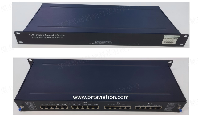
二、 VHF Audio Signal Distributor:Overview,Appearance and Performance
1. The VHF audio signal distributor divides the E&M analog signal 1 output by VHF radio into 4, and then accesses the interphone system, remote controller, recorder and other equipment respectively.
2. The E&M analog signal output by VHF radio consists of four pairs of signals: one pair for receiving, one pair for transmitting, one pair for PTT control, and one pair for noise control.
3. VHF audio signal distributor has four 1:4 components in total, and each audio signal can be cascaded with another 1:4.
4. Appearance, as shown below.

5. Performance:
(1) Audio signal input and output impedance: 600:600Ω.
(2) Dimensions: 4.4 (H) * 60 (W) * 18 (D) cm, 1U chassis.
(3) Weight: 2kg.
(4) Temperature: Indoor -10°C~+50°C.
(5) Relative humidity:Indoor 0~95%(non condensing).
7. Application: Zhangjiajie Airport, Xishuangbanna Airport, Wugang Airport, Nanchong Airport and other China airports.
8. Equipment application connection, as shown below.

三、 Splitters,Combiners(RSC-104A):Overview,Appearance and Performance
1. The RF combiner combines 4 RF input signals into 1 output.
2. The RF splitter divides one input RF signal into four outputs.
3. Used in the VHF radio antenna sharing system, the combiner combines the RF signals output by the 4-channel VHF radio into one channel and outputs them to the VHF transmitting antenna. The splitter divides the RF signal 1 received by the VHF antenna into 4 and connects them to the 4-channel VHF radio receiver respectively.
4. Appearance, as shown below.

5. Performance:
(1) Frequency Range: 100~300MHz.
(2) Maximum Input Power: ≤ 200W.
(3) Insertion Loss: ≤ 0.1W.
(4) Input and Output Impedance: 50 Ω.
(5) Connector: N-type Female.
四、RF Power Divider(RPS-500M): Overview,Appearance and Performance
1. RF power divider, also known as "3dB power divider", divides the RF input signal 1 into 2, with equal power and basically the same RF phase.
2. The S terminal of the RF signal power divider is the RF signal input terminal, and the 1 and 2 terminals are the output terminals. For example, the input power of S terminal is 1W. After passing through the power divider, the output power of 1 and 2 terminals is 0.5W respectively.
3. Appearance, as shown below.

4. Performance:
(1) Frequency range: 5~500MHz.
(2) Maximum input power: ≤ 1W.
(3) Insertion loss: ≤ 0.1W.
(4) Three terminal isolation: ≥ -28dB (isolation between input S terminal and output 1 or 2 terminal).
(5) Input and output impedance: 50 Ω.
(6) Connector: SMA female or N female.
五、RF Multiplexer (VMC108-137M): Overview, Appearance And Performance
1. RF multiplexer, which amplifies the RF signal received by VHF antenna through broadband amplifier, and then divides it into 8, which are connected to other equipment for use.
2. Appearance, as shown below.

3. Performance:
(1) Operating frequency: 118~137 MHz.
(2) Number of RF input ports: 1.
(3) Number of RF output ports: ≥ 8.
(4) Input/output VSWR: ≤ 2.
(5) Isolation between input and output ports: ≥ 25dB. Isolation between output ports: ≥ 20dB.
(6) RF signal strength range of output port: -30dBm~+20dBm.
(7) Adjustable gain range of RF signal (input to all outputs): 0dB~2dB.
(8) Input and output impedance: 50 Ω.
(9) Connector: N-type female.
(10) AC power supply: 110~220Vac ± 15%, 45~63Hz, single-phase.
(11) DC power supply: 12~28Vdc, AC and DC power supply are automatically switched.
(12) Weight: 4 kg.
(13) Dimensions: 4.5 (H) * 60 (W) * 40 (D) cm, 1U chassis.
六.RF Linear Power Amplifier (RPA-50W, RPA-100W): Overview and Performance
1. The input RF signal is linearly pure power amplified and output to the load.
2. Product model: RPA-50W, RPA-100W, RPA-200W, RPA-500W, RPA-1000W.
3. Performance:
(1) Operating frequency: 100~400MHz.
(2) Output power: 50W, 100W, 200W, 500W, 1000W (optional).
(3) Power gain: ≥ 35dB.
(4) Input and output impedance: 50 Ω.
(5) Interface: N-type female.
(6) Input power supply:+28Vdc.
(7) Gain flatness: ± 1dB (full band), ± 0.5dB (10M bandwidth).
(8) Third order intermodulation: -25dB (P.e.P=100W ± 1MHz interval).
(9) Third order intermodulation: -20dB (P.e.P=400W ± 1MHz interval).
 上一篇:
上一篇: 下一篇:
下一篇: