品牌: Bright Aviation,China
型号: RSI-108T112M,RSI-112T118M,RSI-118T137M,RSI-329T335M,R577443010,R570013000,R570313000,LDF4-50A,LDF1-50,FSJ1-50A,FSJ4-50B,AVA5--505。
描述: “Bright Aviation” sells various types of RF isolators, relays, cables and connectors.

Airport facilities and brand suppliers

- Navigation
- Communication Automatic reporting equipment Information Process System VHF Communication Radio VHF radio auxiliary equipment Recorder Intercom System Ground Intercom System Video Surveillance System Cabinet
- Weather
- Surveillance
- Terminal
- Transmission
- Instrument
- Lighting
- Power Supply
- Other Projects
Product


RF Isolator+Relay+Cable+Connector
一、Business
“Bright Aviation”supplies complete sets of products, including after-sales service, technical consultation, spare parts support and other businesses.
二、RF Isolator:Overview,Appearance and Characteristics
1. RF Isolator, also known as "One-Way Isolator", "circulator", is a device that transmits RF signals in one direction.
2. When the RF signal is transmitted in the forward direction, the RF signal at the input end (IN) can be transmitted to the load connected at the output end (OUT) with very low loss. For the reflected signal from the load end, it will be fully absorbed by the dummy load connected at the isolation end (ISO).
3. The unidirectional transmission characteristics of RF signal isolator can be used to isolate the impact of load changes on the input signal source.
4. Characteristics:
(1)Input Power: ≤50W.
(2)Forward Transmission Loss: ≤-1dB (transmission loss between input IN and output OUT).
(3)Isolation: ≥ -20dB (isolation between output OUT and input IN).
(4)Impedance: 50Ω.
(5)Connector: N-type female.
(6)VSWR: ≤ 1.2.
(7)Dummy load: 50W, 0-3GHz,50Ω.
RSI-108T112M RF Isolator | |
| 1、Frequency Range:108~112MHz. 2、Application Equipment: Instrument Landing System (ILS) Localizer. |

RSI-112T118M RF Isolator | |
1、Frequency Range:112~118MHz. 2、Application Equipment: DVOR. | |
RSI-118T137M RF Isolator | |
1、Frequency Range:118~142MHz. 2、Application Equipment:VHF radio. | |
RSI-329T335M RF Isolator | |
1、Frequency Range:329~335MHz. 2、Application Equipment: Instrument Landing System (ILS) Glide Path. | |
三、RF Relay:Overview,Appearance and Characteristics
1. RF relay, in the airport air traffic control equipment, is mainly used for the main and standby switching of two RF signals.
2. The two RF input signals of the relay are switched by the relay, one is connected to the transmitting antenna system, and the other is connected to the dummy load system,
3. RF relay can be divided into single pole (two in and one out) and double pole (two in and two out).
R577443010 RF Relay | |
| 1. Operating Frequency: 0 to 18GHz. 2. Control Voltage: 28V DC. 3. Connector Type: SMA female. 4. Double pole type, 2-channel RF signal input, 2-channel RF signal output. 4. Switching Times: ≥ 100000 times. 5. Application Equipment: ILS, DME, DVOR equipment, etc. |

R570013000 RF Relay | |
| 1. Operating Frequency: 0 to 3GHz. 2. Control Voltage: 28V DC. 3. Connector Type: N-Type Female. 4. single pole, two RF signal inputs, one RF output. 5. Switching Times: ≥ 100000 times. 6. Application Equipment: VHF radio, etc. |

R570313000 RF Relay | |
| 1. Operating Frequency: 0 to 3GHz. 2. Control Voltage: 28V DC. 3. Connector Type: N-Type Female. 4. Single pole, 2-way RF signal input, 1-way RF output. 5. Switching Times: ≥ 100000 times. 6. Application Equipment: VHF radio, etc. |

四、 RF Cable:Overview,Appearance and Characteristics
1. RF cable is the medium that transmits RF signals from one place to another. Common transmission media include air, cable, optical cable, waveguide, etc.
2. Armored RF cables commonly used by airport ATC equipment,as shown below.
LDF1-50,1/4 Hard Fed Rf Cable | |
| 1. 100m cable, working frequency 100MHz, cable loss: -4dB. 2. 100m cable, working frequency 150MHz, cable loss: -5dB. 3. 100m cable, working frequency 300MHz, cable loss: -7.2dB. 4. Mating connector: L1TNM-PL (N-type male); L1TNF-PC (N-type female). |

LDF4-50A,1/2 Hard Fed Rf Cable | |
| 1. 100m cable, working frequency 100MHz, cable loss: -2.2dB. 2. 100m cable, working frequency 150MHz, cable loss: -2.7dB. 3. 100m cable, working frequency 300MHz, cable loss: -3.8dB. 4. Mating connector: L4TNM-PSA(N-type male); L4TNF-PSA (N-type female). |

(1)FSJ1-50A,1/4 Super flexible RF cable. (2)FSJ4-50B,1/2 Super flexible RF cable. (3)AVA5--505,7/8 Hard Fed Rf Cable. | |
1、不常用。 | |
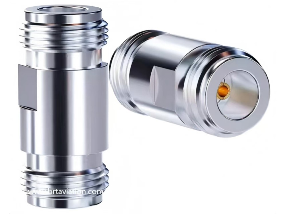
五、 RF Connector:Overview,Appearance and Characteristics
1. RF connector is a RF conversion connector that connects RF cables of various specifications and models.
2. The RF connectors in the list are internationally recognized and commonly used standard models, which can be used all over the world.
3. RF connectors commonly used by airport ATC equipment, as shown below.
4. Characteristics:
(1)Operating Frequency: 0~6GHz.
(2)Characteristic Impedance: 50Ω.
(3)Voltage Standing Wave Ratio(VSWR): ≤ 1.25.
(4)Joint Material: nickel plated brass.
(5)Inner Conductor (needle): gold-plated.
(6)Mechanical Durability: >1000 times.
(7)Operating Temperature: -50 °C~+125 °C.
(8)Relative Humidity: 0~95%.
N male to N male:AXA-NMNM | N female to N female:AXA-NFNF | N male to N female:AXA-NMNF | N male to N female:AXA-NMNF-90 |
|
|
|
|
N male to BNC male:AXA-NMBF | N male to BNC male:AXA-NMBM | N male to BNC male:AXA-NMBM | N female to BNC female:AXA-NFBF |
|
|
|
|
N male to TNC female:AXA-NMTF | N male to TNC male:AXA-NMTM | N female to TNC male:AXA-NFTM | N female to TNC:AXA-NFTF |
|
|
|
|
N female to SMA male:AXA-NFSM | N female to SMA female:AXA-NFSF | N male to SMA female:AXA-NMSM | N male to SMA male:AXA-NMSM |
|
|
|
|
N female to N female:AXA-NFNF-C | N female to N female:AXA-NFNF-F | N male to M male(UHF):AXA-BN108 | N female to M male(UHF):AXA-BN109 |
|
| |
|
SMA male to SMA male:AXA-SMSM | SMA female to SMA female:AXA-SFSF | SMA male to SMA female:AXA-SMSF | SMA female to SMA female:AXA-SFSF-C |
|
|
|
|
N male to N male:AXA-NMNM-3 | N female to N female:AXA-NFNF-3 | N male to N female:AXA-NMNF-31 | N male to N female:AXA-NMNF-32 |
|
|
|
|


 上一篇:
上一篇: 下一篇:
下一篇: