RF Signal Power Divider/Combiner
型号: ZFSC-2-1-N+,ZFSC-2-1-B+,ZFSC-3-1-S+
描述: "Bright Aviation" develops, produces and sells RF Signal Power Splitters and Combiners of various specifications and models from in stock.
一、Business
“Bright Aviation” provides product supply, after-sales service, technical consultation, spare parts support and other services.
二、 Overview
1. RF signal power divider, also known as "3dB power divider", is to divide the RF input signal into two equal parts, regardless of the RF phase difference (generally, the RF phase is basically the same).
2. The S terminal of the RF signal power divider is the RF signal input terminal, and the 1 and 2 terminals are the output terminals. For example, the input power of S terminal is 1W. After passing through the power divider, the output power of 1 and 2 terminals is 0.5W respectively.
3. RF signal combiner, also known as "3dB combiner", combines two RF input signals into one and synthesizes the power without considering the RF phase difference (generally, the RF phase is basically the same).
4. The 1 and 2 ends of the RF signal combiner are the RF signal input end, and the S end is the output end. For example, the input power of terminals 1 and 2 is 0.5W respectively. After passing the combiner, the output power of terminal S is 1W.
三、Performance
1. Frequency Range: Specify the operating frequency.
2. Maximum Input Power: ≤ 1W.
3. Insertion Loss: ≤ -1dB.
4. Isolation: ≥ -28dB (isolation between input S terminal and output terminal 1 or 2).
5. Input/Output Impedance: 50 ohms.
6. Interface: SMA female or N female.
四、Application
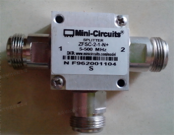
(一)ZFSC-2-1-N+type
1、Operating Frequency Range: 5MHz to 500MHz.
2. Input Power: ≤ 1W.
3. Insertion loss: ≤ 0.1W.
4. Interface: N female.
5. Product appearance, as shown in the figure below.

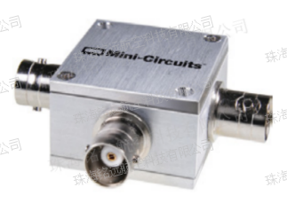
(二)ZFSC-2-1-B+
1. Operating frequency range: 5MHz to 500MHz.
2. Input power: ≤ 1W.
3. Insertion loss: ≤ 0.1W.
4. Interface: BNC female.
5. Product appearance, as shown in the figure below.

 下一篇:RF Relay


 上一篇:
上一篇: