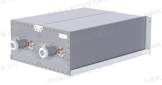
Dual Cavity Filter
型号: SCF118-142M-CH2
描述: “Bright Aviation” R&D, production and in stock sales of SCF118-142M-CH2 Dual Cavity Filter.
一、Business
"Bright Aviation" provides product supply, after-sales service, technical consultation, spare parts support and other services.
二、Overview
1. The dual cavity filter is used with VHF radio.
2. The dual cavity filter has larger path insertion loss and higher out of band rejection. It is used to improve the selectivity of VHF radio receiver and the isolation between multiple transmitting stations, and can more effectively suppress out of band noise and intermodulation interference.
3. The dual cavity filter is composed of two single cavity filters in series to form a band-pass filter with better selectivity. For the working frequency F0 set by the cavity filter, the insertion loss is ≤ -2.5dB to obtain coupling pass. For RF signal with operating frequency F0 ± 500KHz, the insertion loss is ≤ -30dB.
三、Characteristic
1. Frequency Adjustable Range: 118-142 MHz.
2. Input and Output Impedance: 50 ohms.
3. Input Power: ≤ 200W.
4. Number of Channels: 1.
5. Insertion Loss: ≤ -2.5 dB(adjustable).
6. Default Debugging Frequency: 127.5MHz.
7. Reverse Loss: ≤-20dB, typical value ≤-25dB.
8. Frequency Selectivity: ≤-30dB (carrier frequency ± 500KHz).
9. Frequency Tuning Mode: Rotary Knob, Telescopic Movement.
10. Connector: N Female.
11. Size: 42 (L) * 42 (W) * 67 (D) cm.
12. Weight: 14kg.
四、Appearance

五、Measurement Analysis
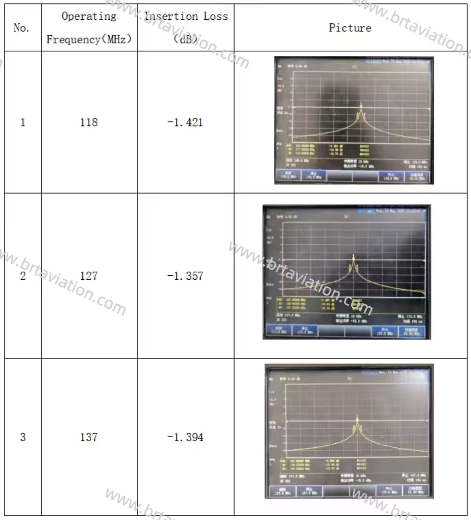
The network analyzer (N9913A) measures the low, medium and high operating frequencies, insertion loss and pictures of the single cavity filter, as shown in the table below.


.png)
 上一篇:
上一篇: 下一篇:
下一篇: